Description
Installation notes
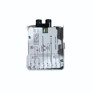
Installation work must be carried out by qualified staff Observe the permissible lengths of the detector cables (refer to «Technical data») Always run the high-voltage ignition cables separately while observing the greatest possible distances to the unit and to other cables Install switches, fuses, earthing, etc., in compliance with local regulations Ensure that the maximum permissible current ratings will not be exceeded (refer to «Technical data») Do not feed external mains voltage to the control outputs of the unit. When testing the devices controlled by the burner control (fuel valves, etc.), the burner control must never be connected Phase and neutral conductors may not be interchanged.
Electrical connection of ionization probe and flame detector It is important to achieve practically disturbance- and loss-free signal transmission: The cable length must not exceed 1 m Never run the detector cable together with other cables – Line capacitance reduces the magnitude of the flame signal – Use a separate cable Insulation resistance – Must be a minimum of 50 M between ionization probe and ground – Soiled detector holders reduce the insulation resistance, thus supporting creep age currents Earth the burner in compliance with the relevant regulations; earthing the boiler alone does not suffice.
Only when firing on gas
Observe the polarity With supervision of the ionization current, the burner controls can detect wrong polarity of live and neutral conductors, in which case they initiate lockout at the end of «TSA» The ionization probe must be protected against electric shock hazard Locate the ionization probe such that – the ignition spark cannot arc over to the ionization probe (risk of electrical overloads) – the ignition spark cannot adversely affect supervision of the ionization current In networks with nonearthed neutral conductor and ionization current supervision, terminal 6 must be connected to burner ground